

**Get expert DIN rail help today →
Three feet of clear working space in front of a panel is code (OSHA 1910.303), but what goes inside matters just as much. This complete guide din rail gives you the short answer: a DIN rail is a standardized metal strip (IEC 60715) for snap‑mounting control gear fast and safe.
You use it to mount breakers, relays, terminal blocks, power supplies, PLCs, and more. The gear locks to the rail with spring clips or screw clamps, so you can add, move, or replace parts without drilling your backplate again.
By the end of this 2026 guide, you’ll know which rail to buy, how to size and mount it, what to avoid, and how to plan a clean layout that a future you will thank you for.
What Is a DIN Rail Mount and Why Does It Matter?
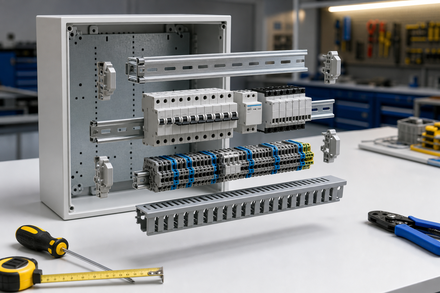
A DIN rail is a cold‑rolled metal profile, most often 35 mm wide “top‑hat” rail, defined by IEC 60715. The profile sets exact width, height, lip angles, and tolerances so devices from different brands fit the same way. That’s why the system works: you get one rail, and almost any control component will snap on.
There are three main rail types you’ll see on real jobs. TS‑35 (aka top‑hat) is 35 mm wide and comes in 7.5 mm and 15 mm heights. TS‑32 is a 32 mm “C‑section.” The G‑section (sometimes called “G‑rail”) is a 32 mm profile with a deep return for heavier loads. In most control panels today, TS‑35 dominates. For a quick visual, see DIN rail on Wikipedia.
So, why did these rails become the universal standard for panel mounting? Speed, repeatability, and service. You can cut a 2 m strip into the lengths you need, deburr, and screw it to a backplate in minutes. Then you snap on terminal blocks, group them with end brackets, and you’re ready to wire.
If a relay fails, one screwdriver twist frees it. No drilling new holes. No slot guesswork.
In addition, the geometry creates a firm “spring bite.” That bite resists vibration, which is key in industrial gear and transit. With stainless or zinc‑plated steel, rails also stand up to corrosion in most indoor sites. As a result, you get a neat, dense layout that you can expand later without tearing the panel apart. This section of our complete guide din rail sets the base: the standard made it universal, and the profile made it practical.
DIN Rail Types at a Glance
At a glance, the common profiles are TS‑35 x 7 and TS‑35 x 15 mm, with the taller 15 mm providing more clip depth for heavier devices. You’ll also see TS‑32 (C‑rail) on legacy relays and timers, so always check the device foot before you buy. For high‑load applications or rail‑mounted busbars, the 32 mm G‑section is the right shape. Pick the one your device foot expects and your lineup will lock in firmly.
Tip: If a datasheet lists “IEC 60715, TH35,” it means TS‑35 top‑hat rail compliance. “TH” is another shorthand for the 35 mm top‑hat profile.
Also Read!
A Beginner’s Guide to 4K Resolution: What It Is, When You Need It, and How to Choose
How to Select and Install a DIN Rail Mount: Step-by-Step
Before you pick up a screwdriver, map what goes on the rail. Count devices, plan space for labels and fingers, and check the enclosure depth. This complete guide din rail process keeps you from repainting corners later.
Step 1: Determine the rail type needed
- Use TS‑35 for 90%+ of modern controls. Choose 7.5 mm height for light gear, 15 mm for heavier gear or if clips specify it.
- Stick with TS‑32 or G‑rail only if your device foot calls for it. If in doubt, check the device rear clip drawing against IEC 60715.
Step 2: Calculate rail length and spacing
- Rail length: Sum device widths (in mm), add 20–30 mm for two end stops, then add 10–20% spare for future gear. For example, 260 mm of blocks + 25 mm stops + 30 mm spare ≈ 315 mm. Round up to the next clean cut (e.g., 320 mm).
- Vertical spacing: Aim for 125–150 mm between rail centerlines for breakers and blocks. For deep gear (power supplies, VFD I/O), push to 160–180 mm.
- Thermal gaps: Leave 5–10 mm between hot devices. Follow each datasheet for exact derating clearances.
Step 3: Mount the rail in the enclosure
- Backplate prep: Mark a level line. Punch or drill two M4/M5 holes at each end. On long rails (≥500 mm) or heavy loads (≥2 kg), add a support every 250–300 mm.
- Fasteners: Use M4/M5 pan‑head screws with lock washers. Where you need bonding, add serrated washers to bite through paint to the backplate.
- Torque: Tighten to the screw spec (e.g., M5 ≈ 3–4 N·m) without bowing the rail. Check level again.
Step 4: Snap components onto the rail
- Start with end on the left, build rightward if your drawings read L→R.
- Hook the top clip, press the bottom in until it clicks. For screw‑clamp feet, seat and tighten to the datasheet torque.
- Group terminal blocks by circuit. Add markers as you go, not after you wire.
Step 5: Secure with end stops and verify
- Add end stops (also called end brackets) on both ends of each device group. Tighten them so devices cannot slide during transport.
- Tug test: Pull each device lightly; it should not rock. Check clearances and conductor bend radius (≥6× conductor diameter for control wiring).
- Bonding: If the rail must be grounded, use a bonding strap or a listed spring clamp to the enclosure PE stud. Verify continuity.
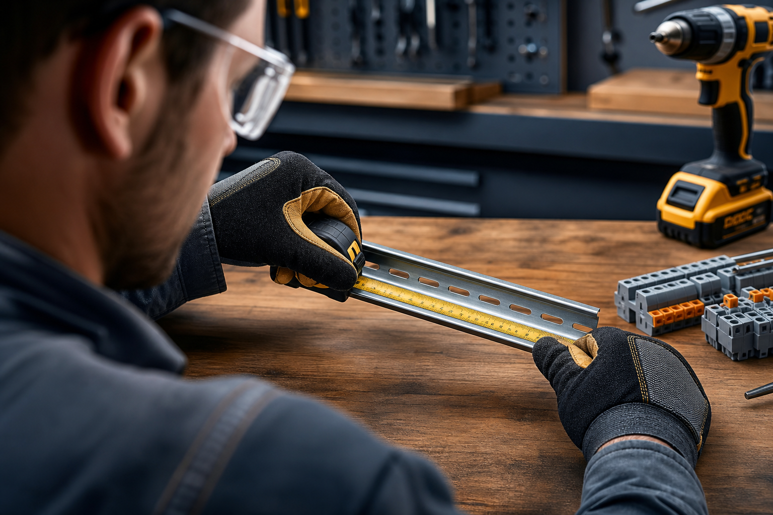
Moreover, label as you build. A clean label strip on terminal blocks and device IDs that match your drawing cut fault‑finding time a lot. Therefore, you prevent guesswork later, especially under time pressure.
**Book a fast DIN rail review →
Common DIN Rail Mounting Mistakes and How to Avoid Them
Even pros slip on the basics. Learn these six pitfalls so you don’t repeat them. This complete guide din rail section keeps your panel safe, serviceable, and compliant.
The big mistakes
The biggest mistakes are all avoidable with a quick check. Using the wrong rail profile, forcing a TS‑35 device onto TS‑32 or G‑rail, loosens the grip and invites failures; always match the foot to the profile. Long rails sag if you overload them without supports, especially on runs over 500 mm or when you mount heavy items like 240 W supplies, and skipping end stops lets vibration walk devices down the rail. Heat is another killer: ignore thermal spacing and you’ll cook gear, so leave 5–10 mm gaps and respect each device’s derating chart. Don’t forget bonding either, because a painted backplate can isolate the rail; use serrated washers or straps, and check depth: device depth + wire bend radius + 10–15 mm safety margin.
Furthermore, don’t crowd the service space. OSHA’s rule for working clearances protects people and hardware. For a quick reference, see OSHA 1910.303 electrical safety.
Quick pre‑power checklist
- Rail screws tight, rail flat, and level
- End stops installed and snug
- Device clips fully engaged
- Labels on blocks and devices match drawing
- PE bond verified from rail to enclosure stud
Also Read!
LPR Camera Guide: How to Choose and Use License Plate Recognition Cameras
Tools, Equipment, and Resources for DIN Rail Projects
You don’t need a full shop. With a small kit, you can build clean panels that pass inspection and are easy to service. This complete guide din rail toolkit covers cutters, enclosures, terminals, and smart gear.
Core tools and cutters
For core tools, a DIN rail cutter leaves square ends without burrs, while a hacksaw works in a pinch if you file all edges after. Pair it with a hole‑marking kit and a drill set, use step bits for gland plates and 3.2–5.5 mm bits for M4/M5 rail screws. A torque screwdriver lets you set device feet and terminal blocks to spec, and a deburring tool plus a file prevent nicked insulation. Round out the kit with a label printer so terminal markers and device IDs match your drawing.
Enclosures and rail hardware
On enclosures and rail hardware, steel or polycarbonate options with removable backplates make work easier, and you should pick IP/NEMA ratings to match the site (e.g., washdown needs higher ingress protection). Cable duct sized 40×60 mm or 60×60 mm fits many control panels; leave 30–50% spare fill for later work. Choose screw‑clamp end stops for higher vibration and use one on each side of a device group. Add support brackets under long rails and under heavy gear to keep spans short and the rail straight.
Terminal blocks and smart devices
For terminals and smart devices, feed‑through blocks in 2.5 mm² and 4 mm² sizes cover a lot of control work, and PE (green/yellow) blocks handle grounds. Multi‑level blocks save width in dense I/O, but plan labels with care so field techs can trace circuits fast. Some NVRs, IIoT gateways, or compact PLCs ship with TS‑35 feet; if you add a small PC or gateway, confirm depth and air flow, or mount it to a sub‑plate.
Moreover, if you’re modernizing video security, you may not need on‑prem servers at all. Cloud‑based AI like VideoraIQ works with existing cameras across 200+ brands, is cloud-based with no need for on-premise servers, and offers smooth integration with most existing surveillance infrastructure. That means you can keep the DIN‑mounted power supplies, PoE switches, and patch gear in your panel, while the analytics run in the cloud. Per the brand’s published stats, the platform monitors 10,000+ cameras, delivers <3 seconds alert latency, and reports 99.4% detection accuracy. In addition, it is GDPR compliant and HIPAA compliant, and is deployed in 7+ countries.
"Installation was quick, and it worked with our current CCTV—no downtime, no extra investment." — Sana Ibrahim, Hotel Security Lead
As a result, you can reserve panel space for network gear and power, then let cloud analytics handle the heavy lift. In 2026, that split saves both space and heat inside your enclosure.
What to Do Next: Planning Your DIN Rail Layout
Plan on paper before you drill. A 1:1 scale layout drawing saves hours and avoids rework. This complete guide din rail wrap‑up gives you a simple plan you can run this week.
Build your layout in four moves
- Sketch the enclosure: Mark duct runs, hinges, and a 30–50 mm margin from edges.
- Place rails: Draw TS‑35 rails with 125–150 mm vertical spacing; leave 20–30 mm at each end for stops and labels.
- Block in devices: Draw to scale. Group by function (power, control, I/O). Leave 10–20% spare width per rail.
- Label plan: Assign tag numbers now. Reserve space for markers, and pick a clear label range for each group.
Next, source parts from one list: enclosure, rails, end stops, supports, terminal blocks, labels, and fasteners. Then build a small starter project, for example, a 12‑circuit terminal panel in a 300×400×150 mm poly box. You’ll gain skill fast without a monster BOM or budget.
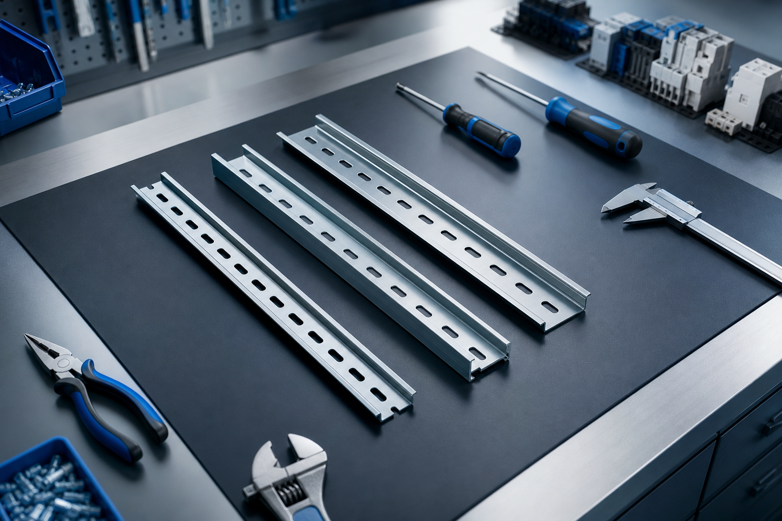 vs G-rail, with annotated dimensions and typical device examples; engineering infographic style)
**Get a quick parts check, free today →
Key Takeaways
IEC 60715 makes rails and devices interchangeable, and TS‑35 is the go‑to profile for most control gear. Size rails by adding device widths, end stops, and 10–20% spare, and support long runs every 250–300 mm. End stops, thermal gaps, and proper bonding are not extras, they prevent faults and drift. Plan the layout first: rails, ducts, and labels on a scale drawing save hours in the build and years in service. Cloud video AI like VideoraIQ can cut on‑panel hardware while keeping your existing cameras in play.
What to Do This Week
Pick a small box, draw a to‑scale plan, and build one DIN‑mounted rail with terminal blocks, a DC supply, and labeled circuits. Document what worked and what slowed you down. Then, apply those notes to your next panel. If you want another set of eyes on your layout or parts list, I’m glad to help.